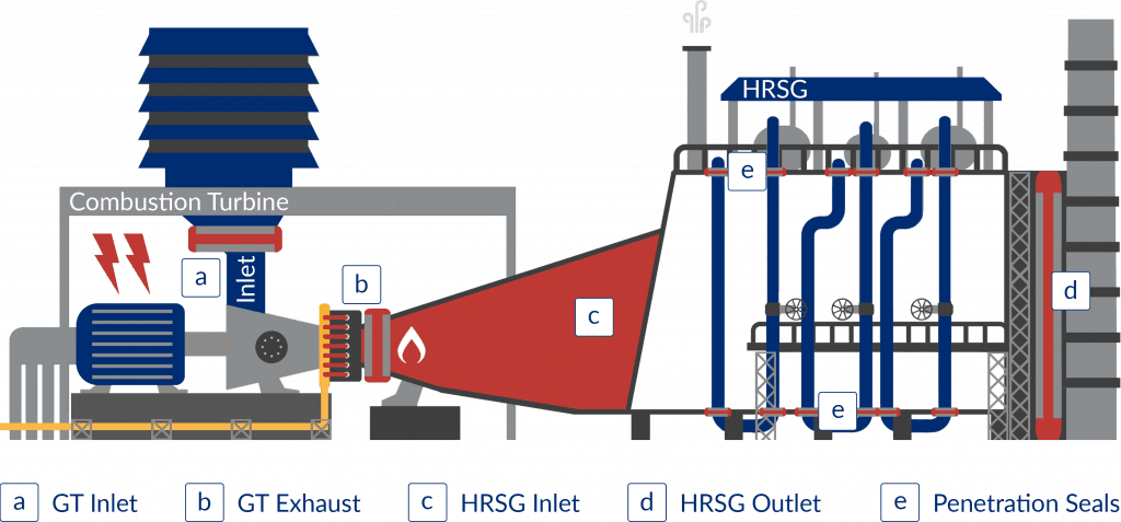
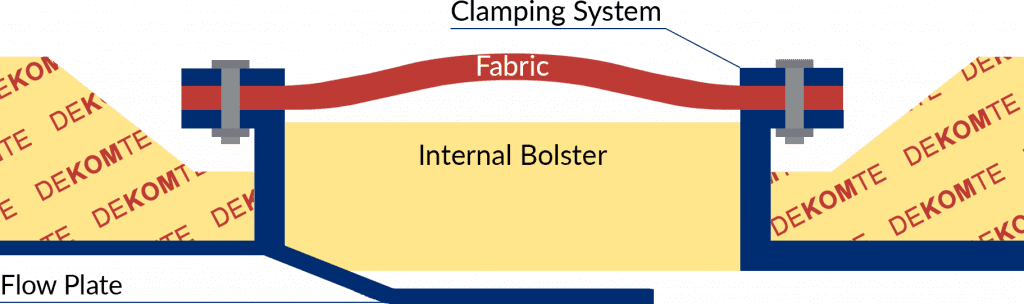
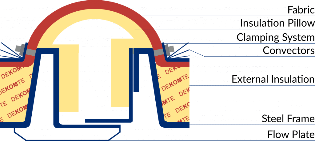
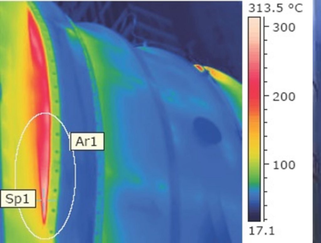
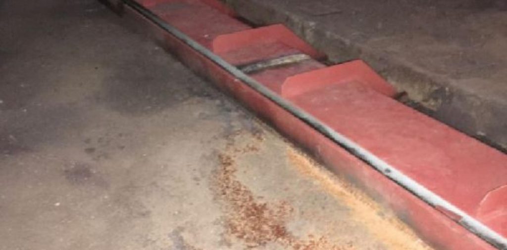
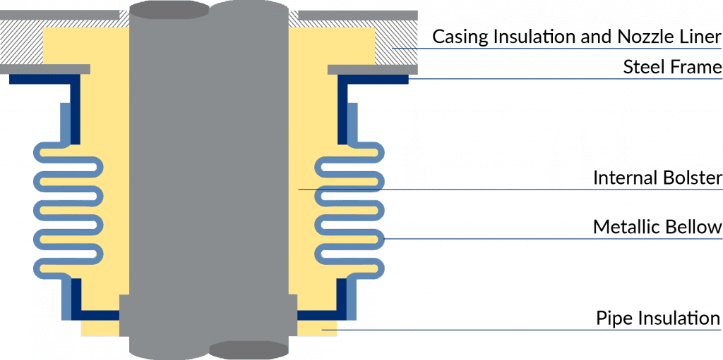
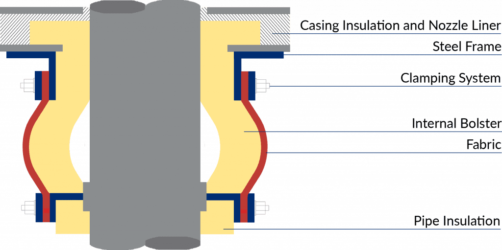
Formed fabrics prevent creasing, crumpling and folding through all movements, essential for high cycling operations. Durable, multi-layer compositions with high temperature membranes and outer protection ensure gas-tightness and prevent stress and damage.

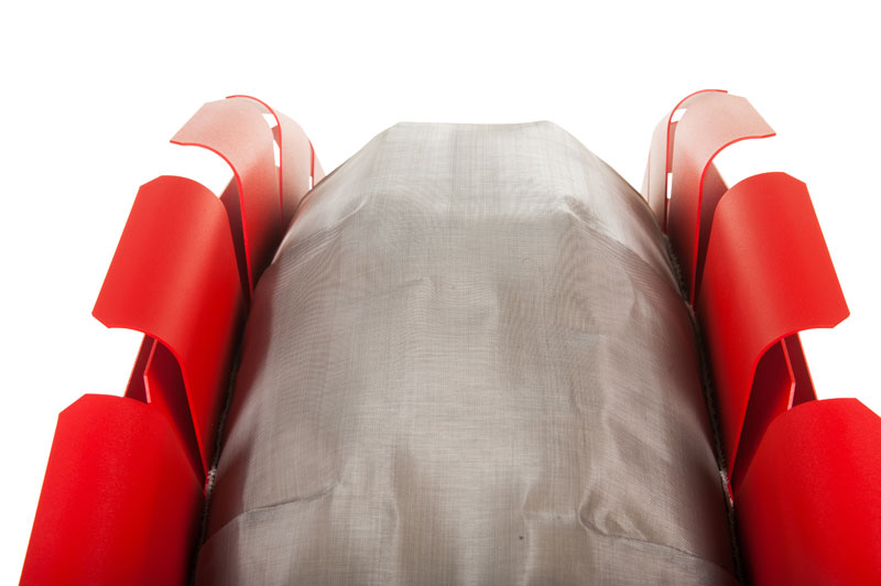

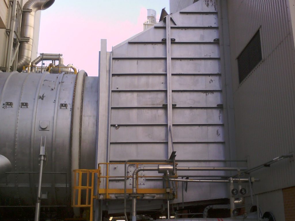


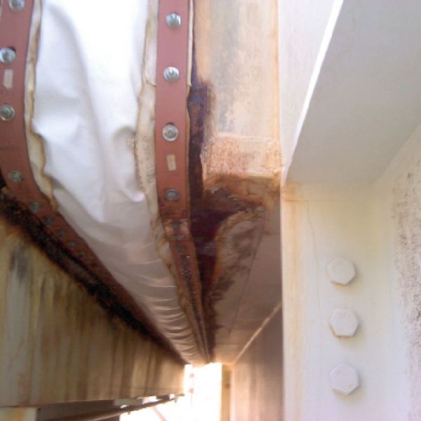
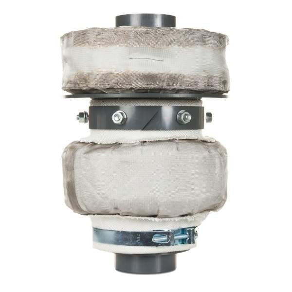

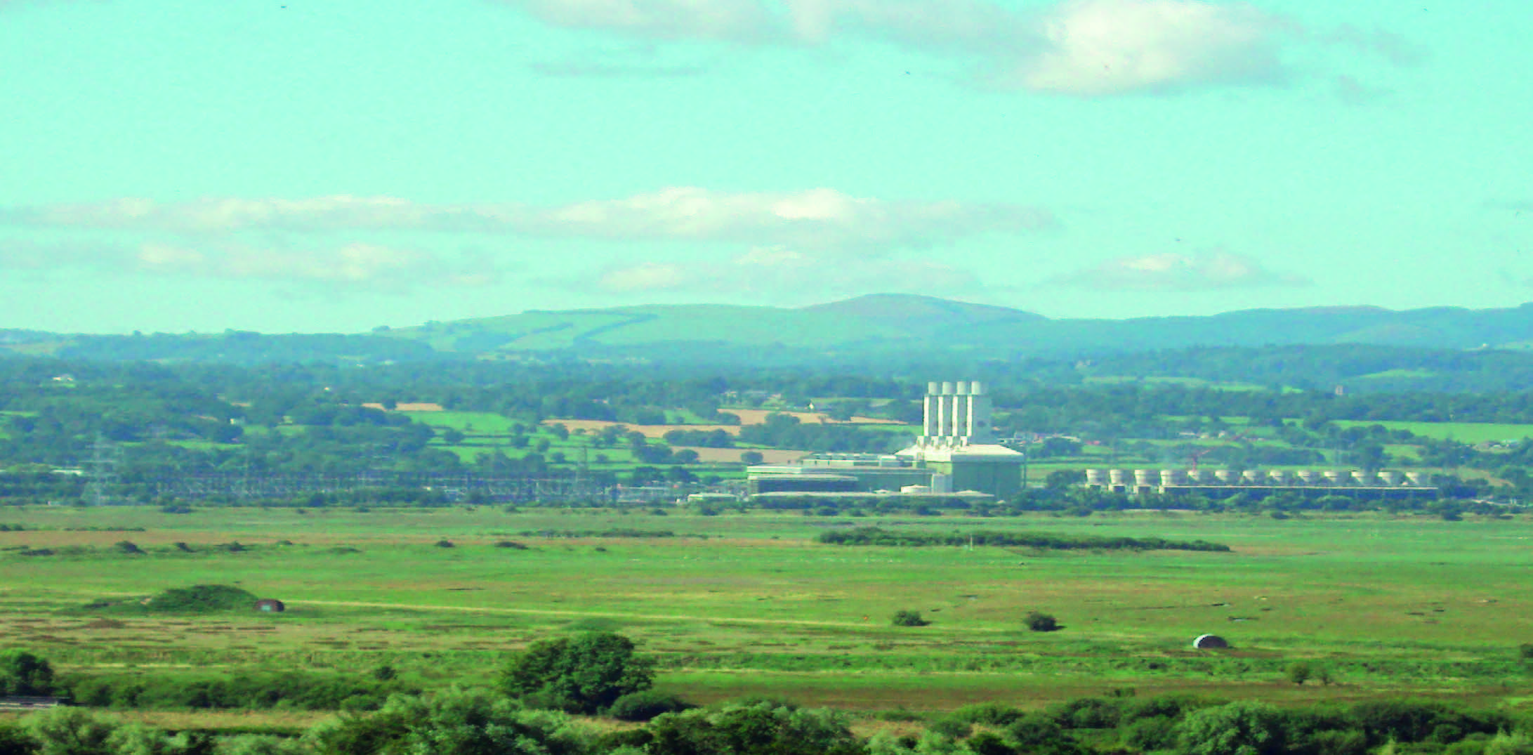 GE 9FA CCGT Power Plant – HRSG Inlet High Cycling Expansion Joint in Wales
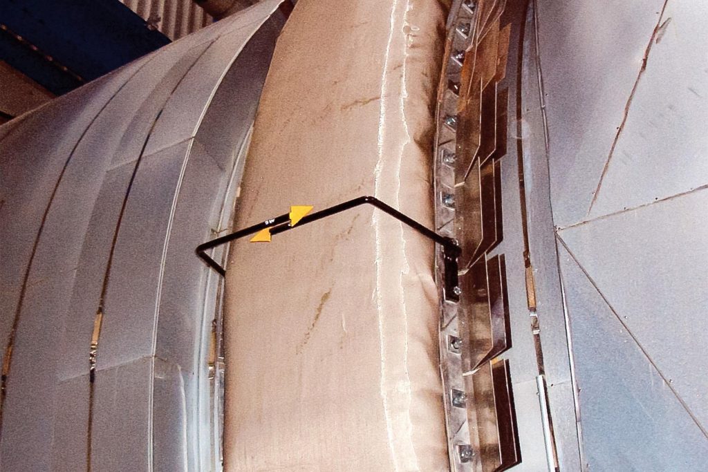
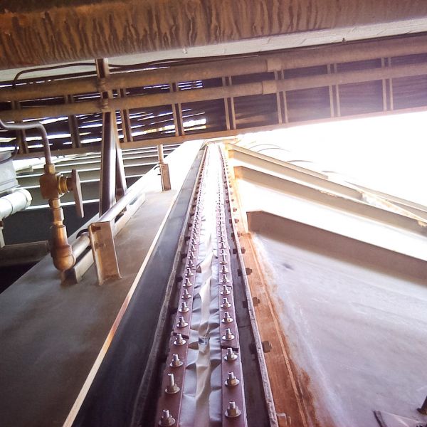
 GE 9FA CCGT Plant – Exhaust Diffuser and Silencer Frame Retrofit in Singapore
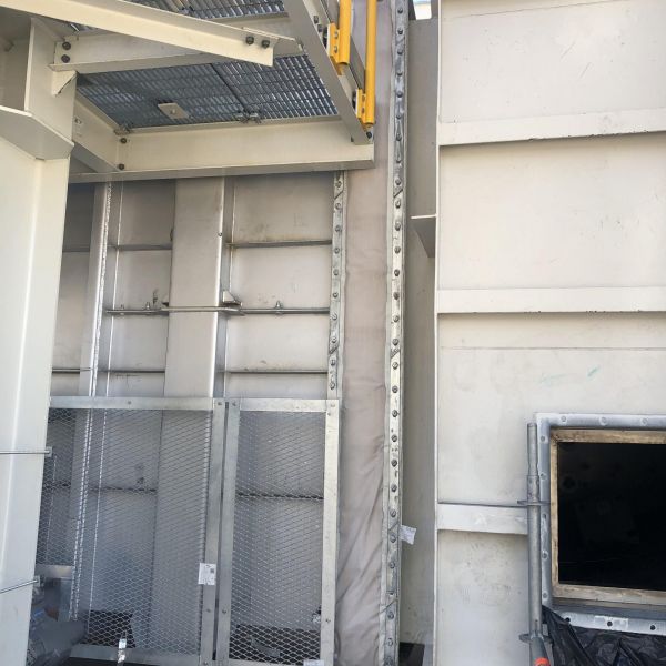
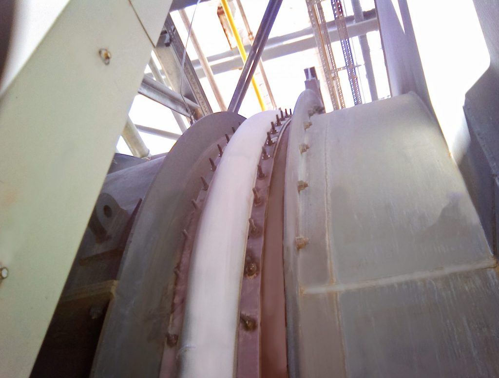
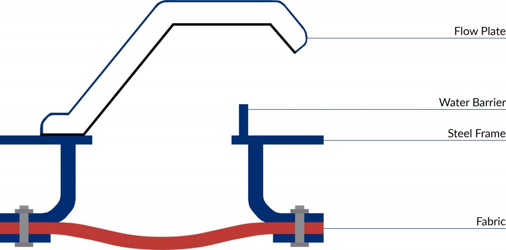
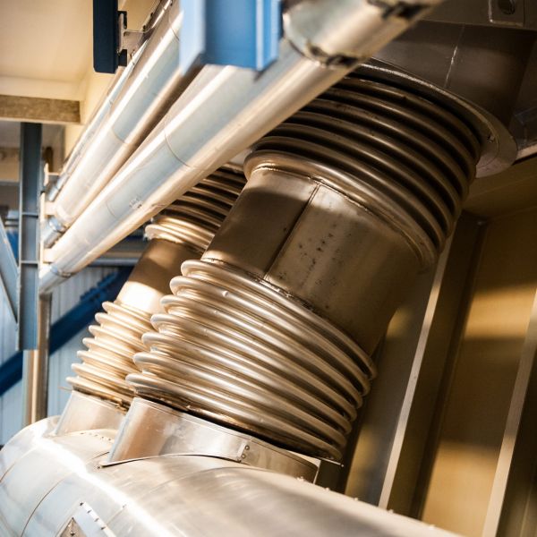
 GE 6FA CCGT Power Plant – GT Exhaust Expansion Joint in England
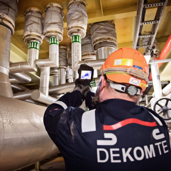