Gas turbine power stations subject the exhaust duct and HRSG casing to extreme stress and fatigue, with the expansion joint being the focus point and relief. In many power stations, the failure and replacement of these expansion joints is considered routine maintenance, with weld repairs to steel parts and duct cracking becoming common place during outages.
Depending on the operating conditions of the site, a DEKOMTE solution can offer lifespans of up to 25 years.
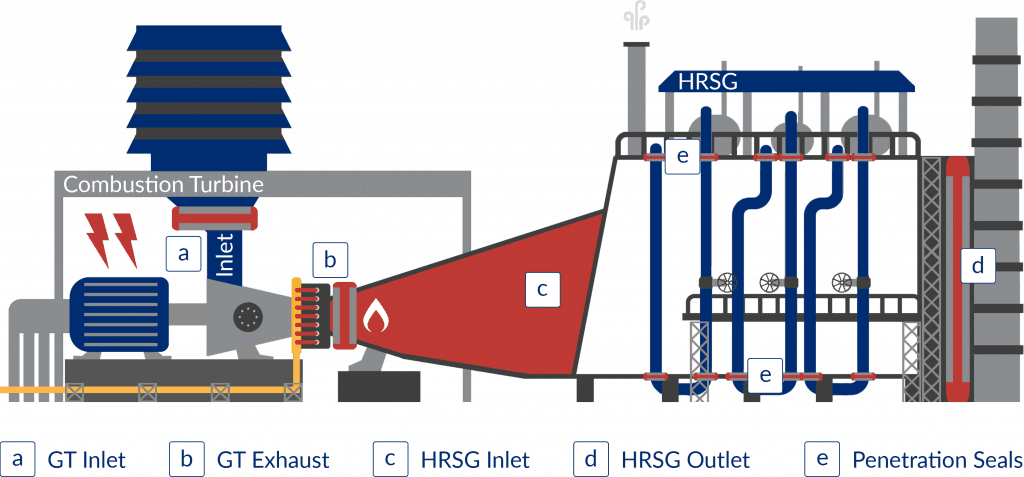
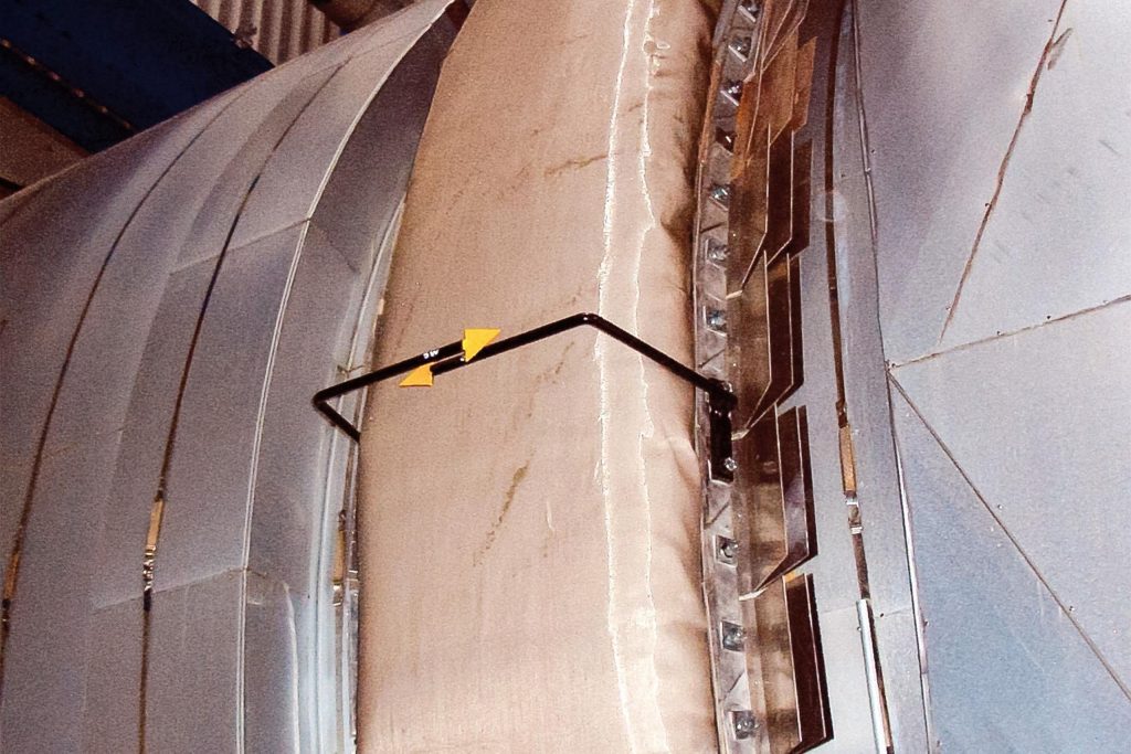
Hot Casing for GT Exhaust / HRSG Inlet
The most critical aspect of hot casing solutions is the steel frame design and its integration to a reliable expansion joint system.
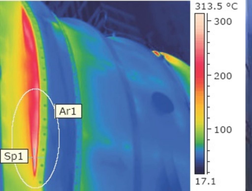
The temperature gradient of the casing to the fabric clamping area can create high stresses, increasing fatigue and reducing life. Square ducts can have more serious problems with the corner regions due to high stresses.
DEKOMTE has many designs for hot casing exhaust systems. In order to establish a suitable design for the casing, support, stiffeners and expansion joint, the stress calculations and fatigue of materials must be considered. Most significant in the calculation process is the cycling and types of starts that a plant will run.

Short-Term Solutions:
- Weld repairs to frame and duct
- Regular replacement of fabric
- External insulation
Long-Term Solutions:
- New steel part arrangement
- Improved duct interface
- New external insulation
- New fabric and bolster design
- New fixing and convector design
Base Load (hot to hot) Cross-Section:

Cycling (hot to hot) Cross-Section:
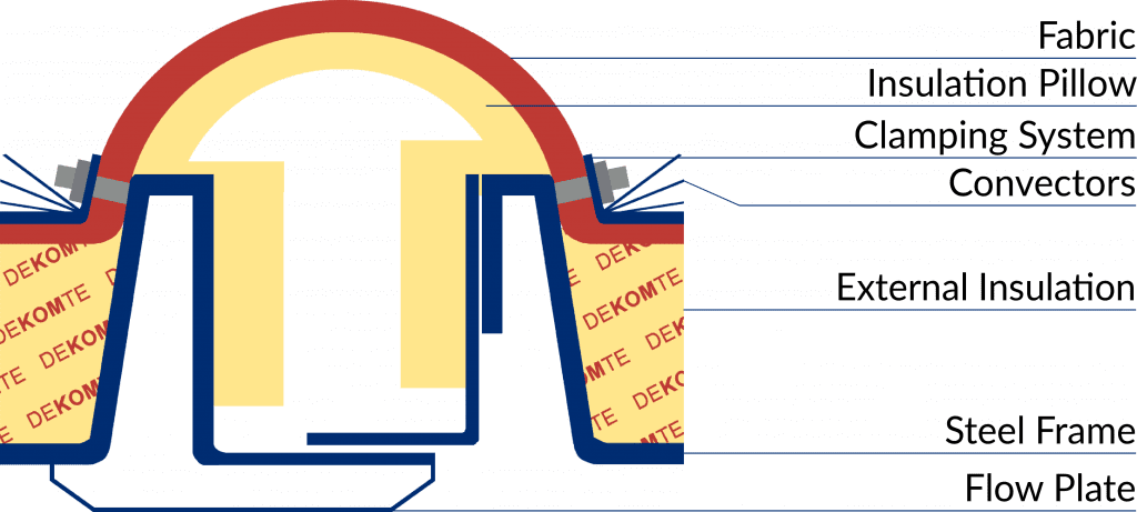
Key elements of the design are:
Both welded and clamped flange systems are available, with consideration given to thermal fatigue, distortion and consistent gas-tightness.
The frame is the most critical part of hot casing solutions. The temperature gradient created on the frame during transient operating conditions of the gas turbine creates high fatigue stresses – resulting in cracking and gas leakage.
Smooth cross-section changes in the duct are essential to reduce turbulence and insulation degradation.
Fully encapsulated and formed insulation bolsters / pillows protect the joints from the inside. Segmented sections of insulation can reduce compression and damage caused by the
movements.
Formed fabrics prevent creasing, crumpling and folding through all movements, essential for high cycling operations. Durable, multi-layer compositions with high temperature membranes
and outer protection ensure gas-tightness and prevent stress and damage.
A gas-tight seal is achieved with proper design of the bolting and clamping to meet the required site pressure.
Managing the temperature profile through the expansion joint, requires control of the radiated and outer surface. The use of convectors achieves this in the clamping area.
The expansion joint system is further protected from excess external radiated temperatures by intelligent integration of the external insulation.
Cold Casing for GT Exhaust / HRSG Inlet
Expansion joints that are installed within a section of duct with internal lining, known as cold casing duct arrangements, experience lower stresses than hot casing arrangements.
Due to the internal insulation, the steel frame isn’t exposed to the same heat stress, however the liner and insulation interfaces across the expansion joint system are critical to ensuring a reliable solution.
Formed fabrics that prevent creasing and folding through all movements, are important for cycling and longer life.
DEKOMTE recommends a review of the connection and internal lining of the joints to ensure that no heat path develops to weaken the design.

Short-Term Solutions:
- Re-insulate missing pockets
- Plate gaps to duct flange
- Reconfigure bolsters
- Install flow plate
- Upgrade clamping system
Long-Term Solutions:
- Designed steel parts
- Improved duct interface
- New seamless internal insulation
- New fabric and bolster design
Base Load (cold to cold) Cross-Section:

Cycling (cold to cold) Cross-Section:

Key elements of the design are:
Both welded and clamped flange systems are available, with consideration given to thermal fatigue, distortion and consistent gas-tightness.
In a cold casing system, the steel frame design is not subjected to the same thermal stresses as long as the frame can remain cold.
Smooth cross-section changes in the duct are essential to reduce turbulence and insulation degradation.
The liner plate should cover the expansion joint space, allowing flexibility by floating / sliding sections. A liner that is seamless over the adjacent flange connections protects the casing and interface to the expansion joint frame.
Fully encapsulated and formed insulation bolsters / pillows protect the joints from the inside. Segmented sections of insulation can reduce compression and damage caused by the
movements.
Formed fabrics prevent creasing, crumpling and folding through all movements, essential for high cycling operations. Durable, multi-layer compositions with high temperature membranes
and outer protection ensure gas-tightness and prevent stress and damage.
A gas-tight seal is achieved with proper design of the bolting and clamping to meet the required site pressure.
HRSG Outlet
The HRSG outlet is a cool condition operating expansion joint, where the temperature conditions are typically a maximum temperature of 150ºC – favourable to a simple material and thin-layered expansion joint. Additionally, the movements are less significant due to the low temperature. The main function is isolating the structure of the duct, HRSG and stack to allow civil structural tolerances, vibration elimination and flexibility from dynamic weather loading.
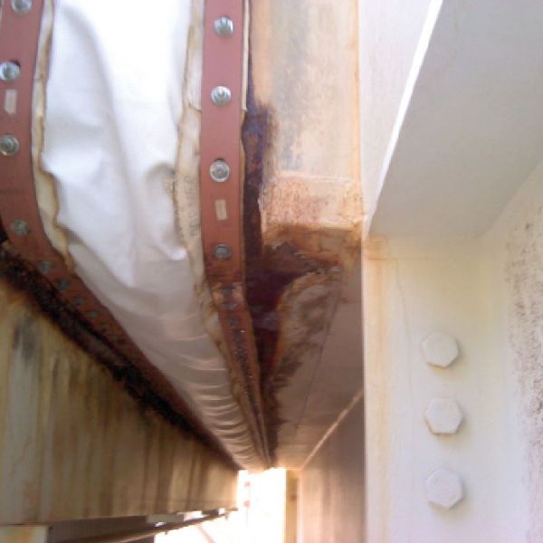
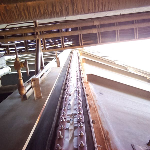
DEKOMTE recommends the retrofit of additional water barriers, drains and integrated flow plate systems. These give the security of
a cleaner, longer functioning expansion joint by eliminating the build-up of water, deposits and debris from inside the joint space.
Careful consideration of the material selection will help a joint at the stack connection reach an expected life of 20 years. Short-term cost savings can result in high maintenance costs on an expansion joint where the cost of access is prohibitive.
DEKOMTE recommends the use of 6mm reinforced rubber expansion joints or multilayer PTFE expansion joints with rubber sealing, as the best solutions to address these main issues:
- Weather tightness
- Water sealing
- And environmental degradation
The effect of these issues includes heavy corrosion on the roof section caused by weather ingress into the duct through the joint flanges, and also on the bottom, caused by water leakage out through the flange from inside the unit.
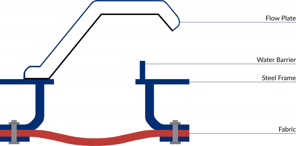
HRSG Outlet Joint Cross-Section:
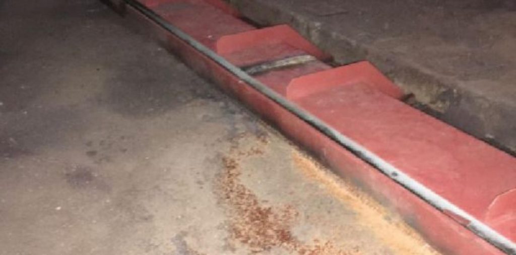
Flow Plate and Water Barrier:
Key elements of the design are:
The integration to the duct is important to reduce weakness and risk in the design. A welded connection is best, with good overlap to insulation and duct cladding system.
The use of the correct material, coating and corner design are important to reach plant lifetime solution. Adding drains, barriers and flow plates are key to extending life and managing
water build up for elimination of corrosion.
A protective flow plate and water barrier prevents condensation, water and debris from pooling in the joint space.
Materials that are stable for the environment and plant conditions will maximise the maintenance life cycle. Fabric compositions that include water sealing materials along with gas-tightness will extend the life of the joint.
A correctly rated and designed bolting system is required to ensure an even distributed sealing pressure is applied to the joint. With particular emphasis on gas-tightness.
Noise attenuation is solved by using high density rubber based joints, or in some cases specially designed acoustic pillows.
Penetration Seals
Penetration seals can be some of the most challenging expansion joints due to their high movement requirements. Particularly on the front modules at GT exhaust temperatures, the floor and side wall seals have large movements in a small cross-section.
Leaking packing glands and mechanical seals require regular maintenance and have a detrimental impact on casings and adjacent equipment – making them an unreliable and expensive solution.
DEKOMTE solutions are gas-tight and ensure no loss of flue gas or heat to the environment.
DEKOMTE offers both metallic bellows and fabric expansion joints.
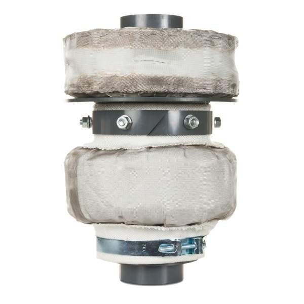
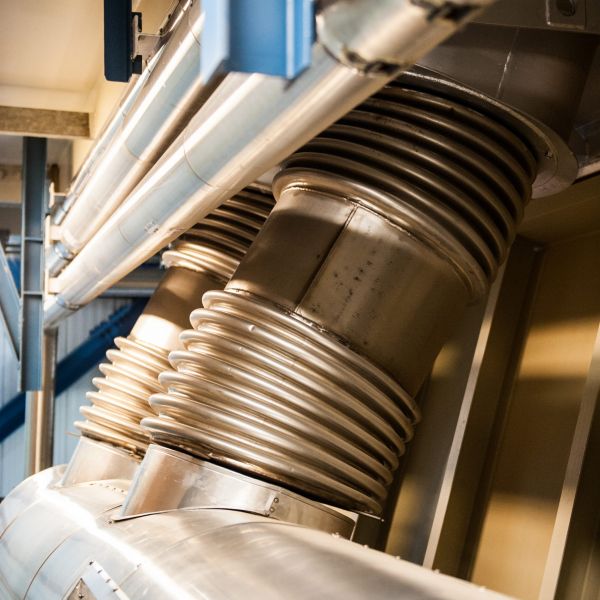
Metallic Bellows:
Metallic bellows offer the lowest initial cost and are therefore favoured for first time installations. However, retrofitting metallic bellows is uncommon due to the necessity to either:
Deliver the bellow in split halves, requiring welding the bellow on-site, or;
Deliver completed bellows, requiring the steam pipe to be cut and welded.
Fabric Penetration Seals:
Due to the problematic replacement of the metallic expansion joints, DEKOMTE has developed highly reliable fabric expansion joint solutions, both as:
- An OEM installation – a product delivered as a fully assembled unit, where cost optimisation is the key function of the design.
- And as a retrofit solution – a product delivered in parts, where longevity, durability and reliability are main focus.
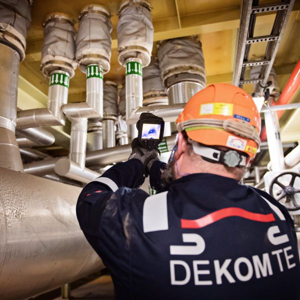
Fabric penetration seals boast the ability to patch, repair and replace in sections, thus minimising downtime or outage.
Metallic Penetration Seal Cross-Section:
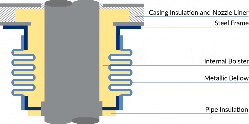
Fabric Penetration Seal Cross-Section:
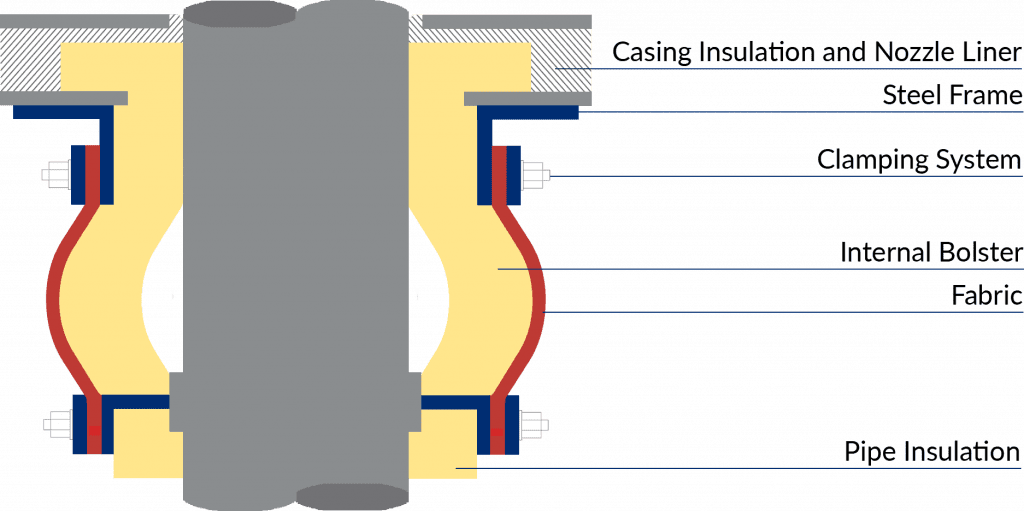
Key elements of the design are:
Intelligent integration of the insulation to the expansion joint pipe collar prevents damage from excess external radiated temperature.
Casing collars align the joints by resetting the pipe concentricity to the casing position. Pipe collars manage temperatures in the seals and offer space for integration of piping insulation to protect the seal from the inside.
Fully encapsulated and formed insulation bolsters / pillows protect the joints from the inside. Segmented sections of insulation can reduce compression and damage caused by the
movements.
Formed fabrics prevent creasing, crumpling and folding through all movements, essential for high cycling operations. Durable, multi-layer compositions with high temperature membranes and outer protection ensure gas-tightness and prevent stress and damage.
A gas-tight seal is achieved with proper design of the bolting and clamping to meet the required site pressure. When possible to attach to the pipes, bolted flanges can eliminate the maintenance required of a circumferential clamp.
The insulation around a nozzle in the casing is subject to highly turbulent gas flow, which invariably pits and pulls the insulation into the gas stream. DEKOMTE avoid this by installing
encapsulated casing bolsters and redesigned nozzle liner plate sections. Ensuring casing temperature is maintained will ensure the further reliability of the penetration seal.

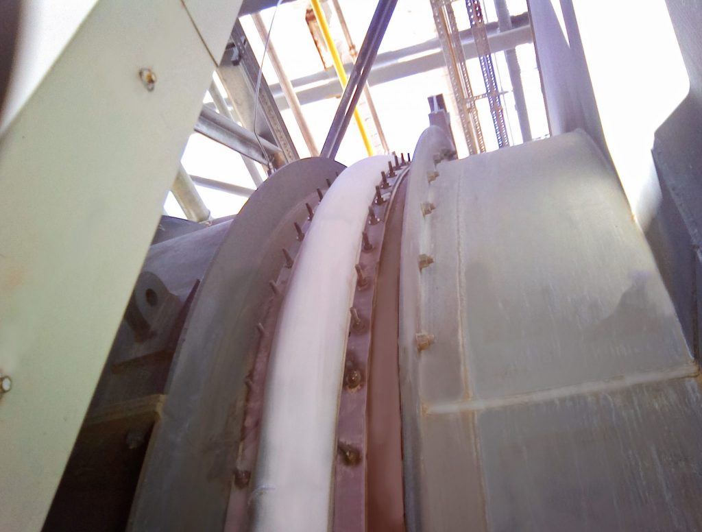
 GE 9FA CCGT Power Plant – HRSG Inlet High Cycling Expansion Joint in Wales
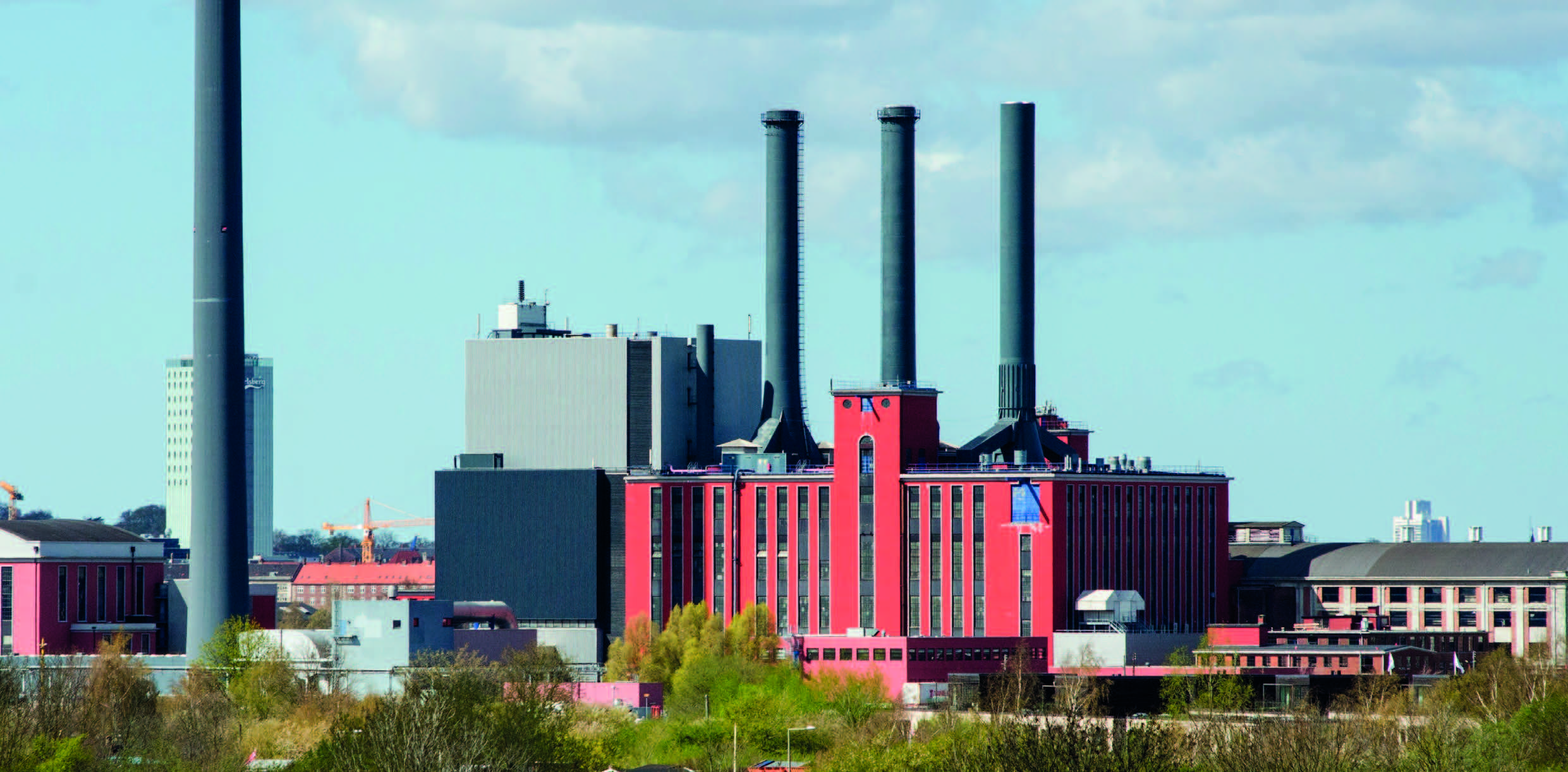 GE 9FA CCGT Plant – Exhaust Diffuser and Silencer Frame Retrofit in Singapore
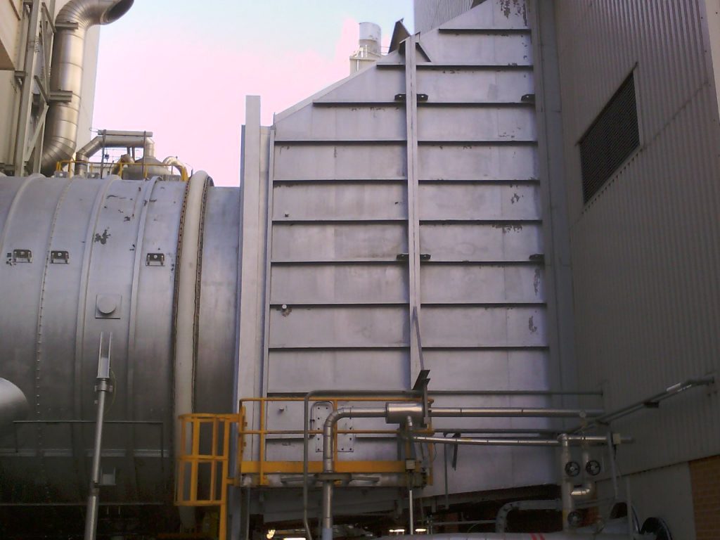
 GE 6FA CCGT Power Plant – GT Exhaust Expansion Joint in England